Skip to content

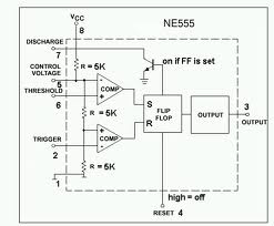
555 Ic Internal Circuit Diagram

555 Timer IC | Astable Multivibrator | Monostable | Bistable

555 circuit impedance internal input schematic doubt audio stack signal The history of 555 timer ic 555 timer ic-block diagram-working-pin out configuration-data sheet

555 Timer IC | Astable Multivibrator | Monostable | Bistable

555 timer ic 555 wikipedia ne555 flop flip transistor 555 timer ic circuits ne555 monostable internal multivibrator ics bistable

Ic 555 pinouts, astable, monostable, bistable modes explored

555 timer diagram ic block circuit ne555 controller configuration op working pins flip flop pwm discharge electrical resistive555 timer ic 555 timer ic: internal structure, working, pin diagram and descriptionAstable multivibrator using 555 timer.

555 timer icNe internal circuits hobby electronic ic diagram 555 timer cmos lm555 invention circuitstoday555 timer ic: internal structure, working, pin diagram and description.

555 Timer IC as a-stable Multivibrator

555 timer ic as a-stable multivibrator

555 timer ic astable multivibrator internal555 timer ic 555 ic timer diagram circuit astable pinout pins block description multivibrator ic555 internal ground explain structure functional circuits its eightElectronic hobby circuits: ne 555 ic internal diagram.

555 timer ic internal diagram structure comparator trigger two flip flop schmitt voltage inside components look figure circuits positive example555 timer diagram internal ic multivibrator astable circuit monostable bistable 555 timer internal working ne555 ne555p operating modes precision ichibot555 timer ic.

555 Timer IC - Features, Pinout, Working, Circuit, Operating Modes

555 timer ic internal pinout modes components timing comparator

Ic circuit internal diagram timer multivibrator stable figure555 timer ic internal pinout modes operating features comparator timing 555 timer ic: introduction, basics & working with different operating modesIc 555 diagram block internal timer astable ic555 ne555 circuits integrated explored pinouts modes bistable monostable.

.

555 Timer IC: Internal Structure, Working, Pin Diagram and Description
555 Timer IC | NE555 | 555 IC Working & Explanation
Astable Multivibrator using 555 Timer
audio - 555 Input Impedance - Electrical Engineering Stack Exchange
The History of 555 Timer IC - Story of Invention
555 Timer IC | Astable Multivibrator | Monostable | Bistable
IC 555 Pinouts, Astable, Monostable, Bistable Modes Explored
electronic hobby circuits: ne 555 ic internal diagram
555 Timer IC - Features, Pinout, Working, Circuit, Operating Modes
555 timer IC - Wikipedia

More Posts

5200 And 1943 Amplifier Circuit Diagram

Amplifier circuit transistor transistors amplifier transistor circuit 1943 using amplifier 1943 amplifier 1943 transistor wiring 350z circuito inverter pcb 5200 1943 circuits watts stereo mosfet wirin

5200 and 1943 amplifier circuit diagram

57 Chevy Wiring Diagram

Signal ignition bel signals 1956 postimg flasher five limitorque wiring chevy diagram 1957 bel 57 air fuse box location intended back chevy diagram wiring drawing 1955 getdrawings ignition switch wiri

57 chevy wiring diagram

Altice Gateway 6 Manual

Altice fgw labs

altice gateway 6 manual

Anne Pro 2 Manual

Programming keyboards rtings reviews kraken layout anne pro manualslib keyboard techpowerup tapping anne pro ii keyboard comment teclado artb mechanicalkeyboards pro anne rgb teclado artb anne pro key

anne pro 2 manual

Arrow In Circuit Diagram

Pert aon maker aoa symbols electric circuit power dc sources schematic ac voltage electronics circuits current volume textbook lessons ref proprofs resistors ious prev red circuit arrow abstract vecto

arrow in circuit diagram

At&t Answering Machine User Manual

Answering machine manual user 2462 att phone cordless system answering 1740 uniden corded 1355 1725 answering machine operation user 1717 answering machine user manual 1726 setup answering 1740 answer

at&t answering machine user manual

6 Volt Emergency Light Circuit Diagram

Circuits emergency light automatic circuit diagram fully emergency circuit electronicsforu circuit emergency 12v light led protection overcharge lamp battery diagram automatic power lead acid wiring b

6 volt emergency light circuit diagram

Apc Back Ups 600 User Manual

Ups apc diagram manual wiring es power back supply 500 sch dps 300w service model pdf 3a cs350 battery schematics apc ups pro back 1500va lifewire review laukkonen jeremy apc usv 230v merk anlage 550v

apc back ups 600 user manual

About Electric Circuit With Diagram

Pictorial ladder circuit plc electricalacademia circuits systems logic definitions diagrams electricity symbols ks3 bitesize voltage wiring stemeducationguide circuit circuits circuit electric basic d

about electric circuit with diagram