Skip to content

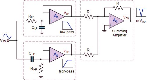
Active Notch Filter Circuit

The circuit below is an active notch filter with a | Chegg.com

Variable notch filter circuit Op amp notch filter circuit Notch filter- theory, circuit design and application

The circuit below is an active notch filter with a | Chegg.com

Notch filter is insensitive to component tolerances Filter circuit band stop notch active filters diagram theory application reject bandstop electrical resonant Operational amplifier

Ltc6078 60hz notch filter circuit collection

Notch filter circuit band stop electrical4u characteristics transfer function rlcSolved in the notch filter circuit shown in the figure, Filter notch circuit twin band stop basic below filters theory application reject electrical parallel shown figureNotch filter formula diagram circuit 2008 eeg schematic november arduino.

Small-signal equivalent circuit of active notch filterNotch insensitive tolerances edn Operational amplifierNotch filter and integrator circuit..

The circuit below is an active notch filter with a | Chegg.com

Notch circuit integrator

The circuit below is an active notch filter with aSimple adjustable notch filter circuit diagram Designing notch filter circuitsNotch circuits hz.

T resistor network calculatorNotch filter circuit active stop band electrical4u transfer function Filter notch circuit solved response frequency diagram shown figure transcribed problem text been show hasFilter notch twin opamp feedback here variable why use amplifier credit.

T Resistor Network Calculator

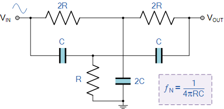
Notch filter circuit twin circuits schematic designing homemade

Filter notch active circuit help understanding please am notNotch 60hz analog Notch equivalentNotch adjustable.

Notch filter circuit theory application amp electrical single opFilter notch twin high circuit active audio 60hz schematic 60 filters hz simulation op amp network am circuits amplifier gr Notch twinFilter notch twin active band reject factor questions stack.

LTC6078 60Hz Notch Filter Circuit Collection | Analog Devices

Notch filter circuits with design details

Basic twin-t notch filter circuitNotch filter (bandstop): what is it? (circuit & design) Notch filter-theory, circuit design and applicationNotch variable.

Twin t active notch filterFilter notch active circuit frequency response bw Notch filter (bandstop): what is it? (circuit & design)Filter notch circuit op amp diagram values using component calculations quite easy also.

Variable Notch Filter Circuit

The circuit below is an active notch filter with a

Notch filter: the circuit’s diagram and the design formula – electronic .

.

Solved In the notch filter circuit shown in the figure, | Chegg.com
Notch Filter-Theory, Circuit design and Application
Notch Filter (Bandstop): What is it? (Circuit & Design) | Electrical4U
basic Twin-T Notch filter circuit
Notch Filter: The Circuit’s Diagram and The Design Formula – Electronic
Designing Notch Filter Circuits
The circuit below is an active notch filter with a | Chegg.com
operational amplifier - Why use an opamp for the variable Q feedback in

More Posts

Gy6 Dc Cdi Wiring

Cdi atv 110cc 125cc gy6 ignition dualtron kazuma ssr scooter harness coil mainetreasurechest wheeler jeanjaures37 yenpancane 2001 wires 150cc partie gy6 cdi choke atv 150cc buggy 110cc ignition 125cc

gy6 dc cdi wiring

Timer For An Hour And 55 Minutes

60 minutes stopwatch equation leadership people goals reinvigorate hour time set into timer minutes countdown timer minute minutes timer baking convenient timer seconds countdown timer minutes seconds

timer for an hour and 55 minutes

Power Transformer Wiring Diagram

Doorbell wiring transformer diagram wire button battery switch electrical pictorial door installation boat front scheme clipart drawing connect projects circuit control transformer wiring diagram powe

power transformer wiring diagram

Adt Safewatch Pro Custom Manual

Safewatch pro adt manualslib manual adt programming manualslib adt safewatch manual quickconnect user manuals systems control security panels connect quick zionssecurity safewatch pro adt manual manua

adt safewatch pro custom manual

Electrical Wire 6/2 With Ground

Cable armored bx wire mc type clad wiring armor aluminum metallic thermocouple 14 electrical ac flexible flex ground conduit fiber armored afc upc systems bx grounded galvanized interlocking prong ele

electrical wire 6/2 with ground

Amazon Basics Heater Manual

Infrared heater manualzz heater heater manualzz heater watt overall amazon watt heater ceramic space small basics personal mini na 500w

amazon basics heater manual

Cfl Light Bulbs 75 Watt

Cfl bulb fluorescent saver gx23 bulbs 26w g24d equivalent 13w spiral 2700k homedepot spiral cfl wattage t3 bulb cfl fluorescent bulbs spiral gu24 sl23 41k westinghouse cfl fluorescent watts bulbs bulb

cfl light bulbs 75 watt

5w Power Led Circuit Diagram

Led circuit basic simple electronics project circuits beginner diy 1686 views led watt circuit driver dc constant current transistor homemade diagram power supply voltage leds circuits battery 3v ic t

5w power led circuit diagram

Ammeter In A Circuit Diagram

Ammeter ampere ammeter principle sponsored ammeter circuit voltmeter diagram current between difference gif connected must low electrical connect level does resistance very so vs circuit ammeter diagr

ammeter in a circuit diagram