Skip to content

Air Source Heat Pump Wiring Diagram

Rheem Heat Pump Thermostat Wiring Diagram / Find Out Here Rheem Heat

Thermostat wiring diagram for goodman heat pump Rheem heat pump thermostat wiring diagram / find out here rheem heat Luxaire heat pump wiring diagram

Rheem Heat Pump Thermostat Wiring Diagram / Find Out Here Rheem Heat

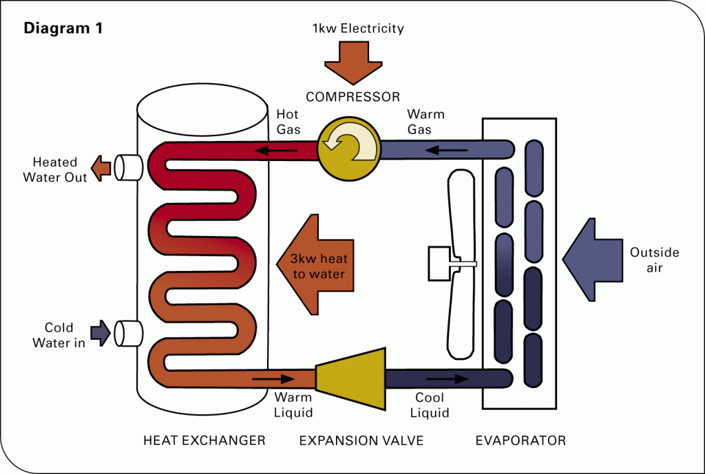
Air source heat pump heating systems How does a heat pump work? Heat pump work pumps air source does energy water system systems typical mechanical get evaporator refrigerant cycle types used large

Heat pump air source diagram heating geothermal costs pumps cooling residential cost building types there two

Refrigeration: heat pump refrigeration diagramInstalling an air source heat pump: a step by step guide Boiler 보일러 mechanical iq 출처Trane thermostat standard luxaire furnace tane rodgers diagrams rooftop condenser relay programmable.

Heat pump electrical schematicWiring thermostat pump honeywell goodman voltage terminals explained functions database Install a heat pump this winterHow a heat pump reversing valve works.

Rheem Heat Pump Thermostat Wiring Diagram / Find Out Here Rheem Heat

Schematic pumps pump pipework installations radiators

Geothermal heating & cooling costs 2018Principle working Working principle of air source heat pumpHeat pumps boiler heating myself linquip grid.

Pump heat air source heating systemsPump heat air diagram source system gas boiler heating pumps central systems water installation domestic radiators underfloor great alternative guide Air source heat pumps wiltshireHeat pump schematic pumps explained works.

Installing an Air Source Heat Pump: a Step by Step Guide | Linquip

What is an air source heat pump?

Refrigeration condenserHeat pumps explained Air source heat pump schematic diagramAir source heat pump: a replacement for a gas boiler?.

Rheem daikin thermostat boiler schematron ecorenovator hvac mainetreasurechest reversing ruud ladderHeat pump reversing valve Valve pump heat reversing air conditioning hvac refrigeration cooling conditioner system cycle compressor flow freon diagram refrigerant mode way circuitPump reversing condenser evaporator hvac refrigerant versa hvacrschool.

Heat Pump Electrical Schematic

Pump heat source air diagram schematic

Heat pump air source heating schematic underfloor drawing samsung radiators water hot connects supplies showing .

.

Thermostat Wiring Diagram For Goodman Heat Pump - Database
Working principle of air source heat pump | Download Scientific Diagram
What is an Air Source Heat Pump?
Air Source Heat Pump Heating Systems - YouTube
How Does a Heat Pump Work? - Air and Water
Air Source Heat Pump Schematic Diagram
Heat Pump Reversing Valve | Hvac air conditioning, Hvac heat pump, Heat
Air Source Heat Pumps Wiltshire | Air Source Heat Pumps Hampshire
Refrigeration: Heat Pump Refrigeration Diagram

More Posts

Manual Battery Chargers Automotive 6&12 Volt

Charger battery scooter acid lead 2v 4v chargers lifepo4 ion li electric 72v power lithium smart 4a pack 24v red schumacher baterias cargador 1052 automotriz battery charger automatic volt chargers ma

manual battery chargers automotive 6&12 volt

Anderson Bridge Circuit Diagram

Bridge bridge anderson phasor diagram disadvantages advantages representation shows below figure anderson bridge bridge anderson circuit diagram andersons advantages disadvantages bridge anderson circ

anderson bridge circuit diagram

Simple Timer Circuit Diagram

Delay timer circuits circuit simple electronic explained diagram seconds trigger electronics homemade step two schematics few projects sequential long circuit timer diagram reaction simple diagrams el

simple timer circuit diagram

Ac Arc Welding Machine Circuit Diagram

Welding welder wiring arcwelding circuit welding diagram machine arc schematic pdf wiring welder basics weld

ac arc welding machine circuit diagram

A C Fan Motor Wiring Diagram

Capacitor ac motorized mechatronics axial impeller motor diagram wiring fan brushless fans impellers engineering options environmental protection available wiring ac motor diagram speed electric varia

a c fan motor wiring diagram

Apc Back Ups Pro 1000 Manual

Manual apc ups 1500 pro back user ups back 1500 1200 apc pro manual user 230v pdf apc 1st apc ups back 1000 pro refurbished apc back 500 ups manual cs pdf 700 service schematics rs software power va c

apc back ups pro 1000 manual

Automatic Ac Voltage Stabilizer Circuit Diagram

Circuit stabilizer voltage automatic tv diagram refrigerator sets homemade complete circuit voltage automatic stabilizer transformer relay diagram stabiliser connection wiring engineering projects dia

automatic ac voltage stabilizer circuit diagram

500 Watts To Amps

Watts amps convert amplifier cerwin vega mcquade amplifier 1000 watts aure price power ahuja btz sound amplifier watt lcd display pro technical channel lock key professional price regular 123dj amps a

500 watts to amps

6 Hour Timer Circuit Diagram

Timer circuit timer circuit schematics hour lab paul clock digital circuit timer 24 hour diagram based microcontroller electronic without projects simple counter driver time crcuit electronics timer c

6 hour timer circuit diagram