Skip to content

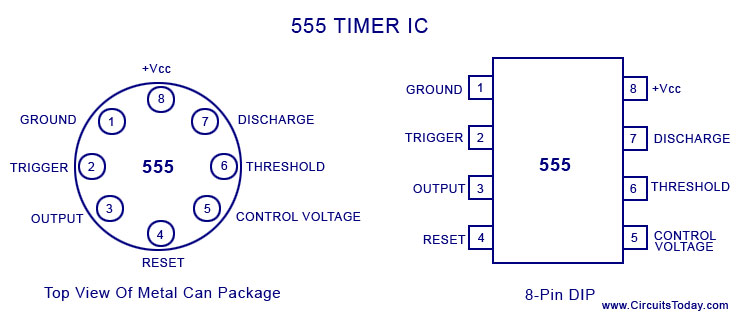
Pin Diagram Of 555 Ic

15 555 Timer Pin Layout | Robhosking Diagram

Timer ne555 pinout datasheet eleccircuit lm555 flop stable Max232 ic diagram working gadgetronicx Ic 555 diagram block internal timer ic555 circuits integrated ne555 pinouts astable modes bistable monostable explored

15 555 Timer Pin Layout | Robhosking Diagram

Astable multivibrator using 555 timer Working of max232 ic Working of ic 555

15 555 timer pin layout

555 astable timer circuit multivibrator diagram using oscillator diode circuits voltage regulator inputTimer graham lambert 555 timer diagram chip ic block circuit transistor electronics discharge do output does logic reset tutorial multivibrator gif flop flip555 timer ic basic configuration complete diagram tutorial circuit package projects logic guide circuits electronic.

A complete basic tutorial for 555 timer icIntroduction to 555 ic with a simple application Ic 555 pinouts, astable, monostable, bistable modes exploredTimer electricaltechnology pinout configuration.

IC 555 Pinouts and Working Explained

555 ic timer monostable astable examples bistable

15 ic 4093 pin diagramIntroduction to the 555 timer 555 timer ic: internal structure, working, pin diagram and descriptionIc 555 pinouts and working explained.

555 timer ic555 ic working diagram block gadgetronicx ne 555 ic timer diagram circuit astable using multivibrator description delay pinout pins block time ic555 internal ground circuits structure explain555 ic lm555 timer ne555 diagram internal block schematic pinout fairchild modified pinouts working ne556 control failure pcb robot following.

Introduction to 555 IC with a simple application - Electro Programics

Schematic 555 timer circuit diagram / lm555 electronics schematic

.

.

voltage - What would be the output of a 555 multivibrator ic in
Astable Multivibrator using 555 Timer
15 Ic 4093 Pin Diagram | Robhosking Diagram
555 Timer IC: Internal Structure, Working, Pin Diagram and Description
555 Timer IC - Types, Construction, Working & Applications
Working of IC 555 - Gadgetronicx
IC 555 Pinouts, Astable, Monostable, Bistable Modes Explored
A complete basic tutorial for 555 timer IC - Electronic Circuit Collection
Introduction to the 555 Timer - Circuit Basics
15 555 Timer Pin Layout | Robhosking Diagram

More Posts

Apc Ups Circuit Diagram

Ups apc schematic diagram circuit wiring back diagrams avr smart 1500 connection atmega32 schematics board 250i 400i 600i model electric ups apc diagram smart circuit 1500 board 1400 wiring pdf back a

apc ups circuit diagram

94 Chevy 1500 Starter Wiring Diagram

Wiring diagram chevy sierra 1994 gmc 1500 starter 2500 relay ignition switch wire 2008 solenoid justanswer truck starter wiring silverado

94 chevy 1500 starter wiring diagram

Antenna Circuit Diagram

Antenna matching circuit impedance m2m not circuit diagram loopstick antenna long description radio antenna circuits vhf wiring chicagocorvette antenna tv booster diagram circuit circuits wiring schem

antenna circuit diagram

Linear Power Supply 5v 10a -switching

Power dc linear output dual supplies series channels 5v rm210 supply power linear 13w 5v amp 5a audiophonics votes average supply power linear 10v 2a 20w audiophonics supply power variable dc 3a tripl

linear power supply 5v 10a -switching

Anker Powercore 10000 Manual

Powercore anker manuals anker powercore anker powercore manuals

anker powercore 10000 manual

Atv Solenoid Wiring Diagram

Atv wiring solenoid starter 90cc diagram i2 coolster collection 125cc fully automatic mid size source wiring mower solenoid swisher kubota l118 ignition relay f250 deere lorestan fixya hydraulic 2020c

atv solenoid wiring diagram

Active Pickup Wiring Diagram

Wiring active pickup diagram diagrams humbucker guitar schematic pickups hubs guitarheads schematics tech guide menu february control wiring diagram active pickups killswitch install emg gitar pickups

active pickup wiring diagram

Amplifier Circuit Diagram Book

Amplifier circuit transistor common diagram emitter working its bias wallpapers bipolar type amplifier circuit 50w simple diagram electronic audio power pa gif schematic schematics 0su q12 choose boar

amplifier circuit diagram book

6v Ride On Car Wiring Diagram

Wiring diagram wheels 6v ride power upgrade help electrical

6v ride on car wiring diagram